Publications
Three Sensor Types Drive Autonomous Vehicles


Introduction
Fully autonomous driving by the model year 2021/2022 with security level 4 or 5 requires the use of multiple redundant sensor systems. Today’s systems for semi-autonomous driving use various numbers and designs of radar and camera systems. The design of high-resolution, affordable LIDAR systems with ranges up to 300 m are still in the pre-development stage. The majority of today’s automotive manufacturers assume that for fully autonomous driving, all three systems are required.
This article describes the main features of these systems, their advantages and disadvantages, and the current state of the technology. We discuss the semiconductor components required for intelligent and cost-optimized solutions from the manufacturer‘s perspective.
Overview
What autonomous driving means is not always clearly defined. If a car has cruise control and speed limiter function, is that autonomous driving? Certainly not, but what if there is automatic distance and adaptive cruise control (ACC) and the driver can briefly, under certain conditions, leave control to the car itself? The different classifications of autonomous driving are shown in Table 1. These classifications are the adopted standards: J3016 of the international engineering and automotive industry association, SAE, and in Europe by the Federal Highway Research Institute.
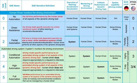
Level 0: Driver only: the human driver controls everything independently, steering, throttle, brakes, etc.
Level 1: Assisted driving: assistance systems help during vehicle operation (Cruise Control, ACC).
Level 2: Partial automation: the operator must monitor the system at all times. At least one system, such as cruise control and lane centering, is fully automated.
Level 3: Conditional automation: the operator monitors the system and can intervene when necessary. Safety-critical functions, under certain circumstances, are shifted to the vehicle.
Level 4: High automation: there is no monitoring by the driver required. Vehicles are designed to operate safety-critical functions and monitor road conditions for an entire trip. However, the functions do not cover all every driving scenario and are limited to the operational design of the vehicle.
Level 5: Full automation: operator-free driving.
As of today, no car manufacturer has achieved level 3 or higher in production, although several have produced demonstration vehicles. The legislature of some countries is working on a possible admission of “Level 3” vehicles, which are expected to be available in 2020/21.
Which sensors are required for autonomous driving from Levels 1 to 5? As already mentioned, there are three main groups of sensor systems: camera-, radar-, and lidar-based systems. Although, for parking, ultrasonic sensors are available today and are widespread, they are of minor importance for autonomous driving. Camera and radar systems are in the Level 1 and 2 vehicles today and are prerequisite for all further levels of automation.
Today’s Camera Systems use CMOS image sensors – HD with 1 to 2 megapixels. Mono and stereo cameras in conjunction with radar systems provide a precise evaluation of speed and distance as well as the outlines of obstacles and moving objects. Radar sensors for short-range (24 GHz) or long range (77 GHz) are located in the front and back of the vehicle to monitor traffic. These can monitor ranges from a centimeter up to a few hundred meters.
Lidar systems today are only very rarely used in serial production. The potential of this technology is not yet fully explored because of cost and availability reasons.
The following sections provide detailed descriptions of the individual sensor systems, the current status of future developments, and the advantages and disadvantages of each.
Camera
Rear and 360° Cameras
Video images provide most of the details for the human driver but are also suitable as an input parameter for highly automated driving. Rear and 360° cameras support the driver with a better representation of the environment outside the vehicle. Today, two-dimensional cameras are widely available to display images and sometimes superimpose additional information on the display such as the steering wheel angle. Luxury class car makers are beginning to install cameras with virtual, three-dimensional image displays.
For the three-dimensional image to be realistic, usually the input signals from four to six cameras are required, and it is necessary to pay particular attention to the ‘image stitching’ to avoid loss of image information or generation of ghost images. Both 2-D and 3-D cameras require image sensors with very high dynamic range of more than 130 dB. This high dynamic range is absolutely necessary to deliver a clear image even with direct sunlight shining into the lens. The best available image sensors on the market have a dynamic range of 145 dB with a 24-bit deep interface to the ISP (image signal processor). This dynamic range is well above what common lens systems can offer.
Another important quality feature is the image sensor’s light intensity. Currently, the best one available on the market has an image sensor Signal to Noise Ratio (SNR)=1 for 1 mlx (Millilux) illumination and a frame rate of 30 frames per second.
Today’s automobile rear and 360° video systems usually have a centralized architecture. This means that a central control unit processes the raw data of four to six cameras. Since the processing is done in software, the processor faces tough requirements. Additional FPGAs are necessary for specific hardware acceleration, which in such a system, causes a high-power loss. Modern data compression methods also require large storage capacities.
The following figure shows another approach, which is based on the distribution of image processing to the cameras and the subsequent data distribution via Ethernet to the head unit (ECU that contains the control for the main display), which completes the image aggregation and presentation. The individual images are preprocessed within the camera and then sent to the main processor in the head-unit using low-latency H.264-compression via an Ethernet interface. Figure 2 shows the expected development of automotive camera systems from analog to digital.
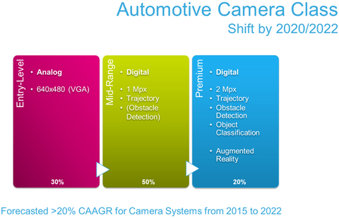
By 2020, the majority of camera systems will be digitally based. Current digital camera systems receive raw data which is then processed and forwarded to the display unit for image display. This procedure is shown in figure 3.
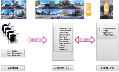
The decentralized approach eliminates the Camera Control Unit (ECU) completely, leaving only the smart camera and the head-unit. For further clarification, this approach has two processing steps within the camera as well as in the central camera control unit, as detailed in figure 4.
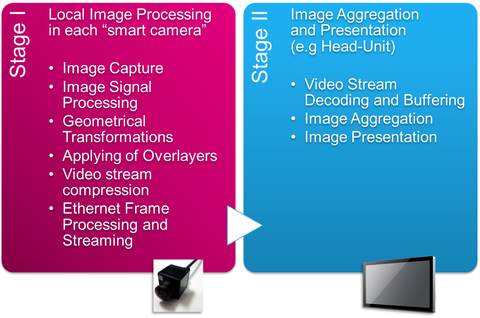
In the first stage (within the smart camera), the image is processed and the geometrical transformations such as the fish-eye EQ, over layer, and image compression is done as well as the Ethernet processing and streaming. The second stage (within the central camera module) then takes over the video decoding, the intermediate storage as well as displaying the image on the screen.
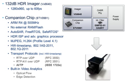
This approach makes it possible for a rear camera to compress and send the data via Ethernet to the head unit. Figure 5 shows the technical details of such a highly integrated, smart rear camera.
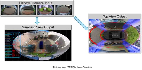
A further application for smart camera is to merge the video signals from four cameras into a 360-degree view as shown in figure 6.
Forward-Facing Camera Systems
These camera systems are systems for medium to high ranges, such as in the area between 100 and 275 yards. These cameras use the algorithms to automatically detect objects, classify them, and determine the distance from them. For example, the cameras can identify pedestrians and cyclists, motor vehicles, side strips, bridge abutments, and road margins. The algorithms are also used to detect traffic signs and signals.
Medium range cameras essentially warn the driver about cross-traffic, pedestrians, emergency braking in the car ahead, as well as lane and signal light detection. High range cameras are used for traffic sign recognition, video-based distance control, and road guidance.
No color-accurate signal reproduction is specified for these camera systems, as only the direct raw data of the image sensor is used. As a rule, a color filter with an RCCC (Red Clear Clear Clear) matrix is used, which provides a higher light intensity than the RGB filter (Red Green Blue) used in most imaging cameras. ‘Red Clear Clear Clear’ indicates a pixel with a red color filter and three with a neutral (clear) color filter.
The main difference between cameras for medium and high range is the aperture angle of the lenses or FoV, field of view. For medium range systems, a horizontal FoV of 70 ° to 120 ° are used, whereas cameras with a wide range of apertures use horizontal angles of approximately 35°.
Future systems will try to cover mid and high ranges exclusively with an optical system. In order for this to succeed, image sensors in the future are likely to have more than 7 million pixels.
RADAR
Accident statistics show that 76% of all accidents are based solely on human error. In 94% of all cases, human error is involved [1], [2]. ADAS (Advanced Driver Assistance Systems) require several radar sensors that make a crucial contribution to the overall function of autonomous driving. Of course, the word RADAR stands for Radio Detection And Ranging, which means the detection and localization of objects using radio waves.
Current radar systems are either based on 24 GHz or 77 GHz. The advantages of the 77 GHZ lie mainly in the higher accuracy for distance and speed measurements as well as in the more precise angular resolution. Further advantages over 24 GHz are the smaller antenna size as well as the lower interference problem. The main differences lie between SRR (Short-range radar) applications and MRR/LRR (mid-range radar, long-range radar) applications.
Short-range radio applications include:
- Blind Spot Detection (Blind Spot Monitoring)
- The lane and the lane-change assistant
- Rear end radar for collision warning or collision avoidance
- Park Assist
- Cross-traffic monitoring
- Examples for MRR/LRR applications are
- Brake Assist
- Emergency braking
- Automatic distance control
The SSR applications are essentially designed to replace ultrasonic sensors and to support highly automated driving. To this end, sensors are placed at each corner of the vehicle, and a forward-looking sensor for long range detection is positioned on the front of the vehicle. For a ‘cocoon’ radar system, extra sensors are placed on each side mid-body.
Ideally, these radar sensors would use the 79-GHz frequency band with a 4-GHZ bandwidth; however, global frequency specifications so far allow only 1 GHZ bandwidth at 77 GHz. Today, a common partitioning for a radar MMIC (monolithic microwave integrated circuit) are three transmission channels (TX) and four receive channel (RX) to be monolithically integrated. Under discussion in the industry is whether it makes sense to integrate base band processing in the MMIC or whether it is better to concentrate on a raw data radar sensor.
The difference is that the output of the baseband processor provides so called pre-targets, which means it is preprocessed data such as unverified information on speed, distance, signal strength, horizontal angle, and vertical angle for each detected object. The raw data radar sensor provides unfiltered raw data, which the ECU then processes. Figure 7 shows the architecture of such a raw data radar sensor.
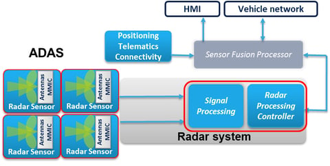
In this case, the base band is integrated with the radar process controller. The radar sensor provides unfiltered raw data to the process controller. This approach has several advantages. First, the integration of base bands within the process controller saves silicon surface space and associated costs. The reason is that a relatively simple CMOS-fine-line can be used rather than a specially optimized technology for RF applications.
A further advantage is the relocation of the power loss from the radar sensor into the control unit. Since the controller has much more space than the radar sensor, it is easier to control the power loss at this point.
Finally, because there is no loss of data by filtering or compression, the ability to access the radar sensor’s unfiltered raw data provides more possibilities for signal processing and flexibility. Even the required data rate for such a raw data radar sensor is not a problem since data can be transferred using a MIPI CSI-2 communication interface (see figure 8).
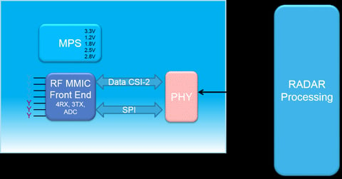
This interface is already in use today, for example, in video surround systems. This architecture fits in very well with the raw data radar sensor shown in Fig. 8 because the interface includes four data lines, which fit the four receiver outputs, each with 12 bits of the radar MMIC. The bandwidth of the communication interface is also well suited with 1 to 1.5 Gbit/s.
This partitioning of the radar sensor then simplifies the data fusion of the video and radar data and future LIDAR data since the same communication interface can be used (see figure 9).
A prerequisite for the development of MMICs are dedicated high-frequency (HF) technologies to realize the frequencies (24 GHz or 77 GHz) and the corresponding output power.
Today, SiGe hetero bipolar transistors are already in use for the HF part, and monolithic 130-nm CMOS processors are used for logic integration. For some years now, ST has produced 24-GHz MMIC in a BiCMOS9 technology. The development of the 77/79-GHz baseband uses the new BiCMOS9MW technology with a minimum 130 Nm CMOS structure width.
For future radar systems with higher frequencies such as 122 GHz, ST has developed a B55-technology. This technology provides SiGe hetero bipolar transistors with a transit frequency of more than 320 GHz and makes it possible to integrate the corresponding CMOS digital logic in 55 nm.
Beyond the optimized BiCMOS technologies, STMicroelectronics has the ability to implement SoC (System on Chip) integration through the company-developed FD-SOI technology. It has a lithograph of 28 Nm. Figure 9 shows the current roadmap of MMICs. One of the latest developments in the 24 GHz range is the A431-block, which contains a transmitter and three receivers. The 26 GHz baseband components shown in the roadmap were developed for the US market.
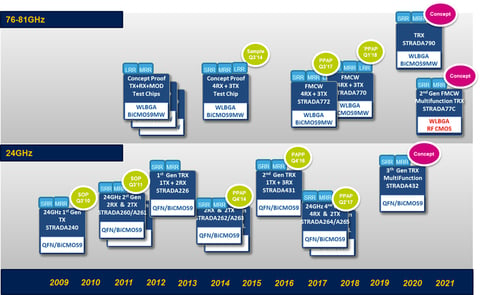
Of the 77/79 GHz baseband components shown in the roadmap, the A770/A772 are currently in development. The A770 MMIC transceiver shown in the block diagram of Fig. 10 is already a highly integrated solution.
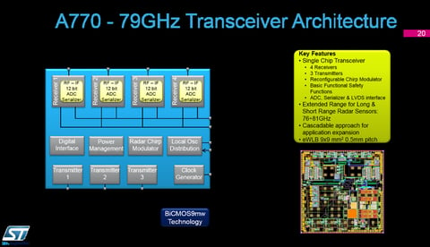
The A770 is a monolithic integrated transceiver that includes three transmitters, four receivers, a configurable ramp generator, an integrated ADC (Analog to Digital Converter), and a MIPI CSI II Interface. This block can be cascaded even more transmit and receive channels as needed for the application. The block is in a ceramic EWLB housing with a size of 9 mm x 9 mm. The A770 is suitable for medium and long-range applications.
Currently under feasibility study for future radar sensors is a monolithic SoC integrating both the radar and baseband functions. As described before, the advantages of a raw data radar sensor in such a highly integrated solution are being studied in great detail as well as possible disadvantages, using market studies looking at commercial considerations.
LiDAR Sensor
Lidar is a relatively new system in the automotive sector and is beginning to gain traction. The system and semiconductor manufacturers working on new and improved solutions today are targeting 2020/21 model use.
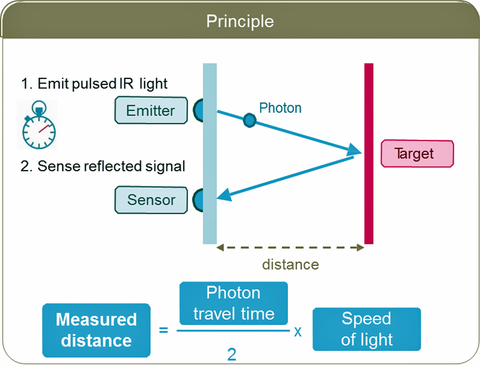
What is LIDAR? As mentioned above, it is an acronym for Light Detection And Ranging and is a laser-based system. In addition to the transmitter (laser), the system requires a highly sensitive receiver. Used primarily to measure distances to stationary as well as moving objects, the system employs special procedures to provide three-dimensional images of the detected objects.
Today, anyone can buy a distance meter using this principle from almost any home and building supply store to accurately determine distances up to a few yards. The challenge for a driver assistance system is to ensure that it will function under all possible environmental conditions (temperature, solar radiation, darkness, rain, snow), and above all, recognize objects up to 300 yards away. And of course, all this in large-scale production at the lowest possible cost and smallest dimensions.
Lidar systems are not new and have been in use in industry and the military for many years. However, these are complex mechanical mirror systems with a 360° all-round visibility that capture spatial images of objects. At costs of several tens of thousands of dollars, these mechanical systems are not suitable for large-scale deployment in the automotive sector.
Today, there are two general trends in the automotive market for the future: infrared LIDAR systems that with the aid of a Micro-Electro-Mechanical System (MEMS), use a rotating laser, or a solid-state LIDAR.
Before briefly discussing the differences between these technologies in detail, a few comments on the receiving system. The task is to recognize the light beams emitted as well as reflected from the object. The detectors must be extremely sensitive and able to measure single photons. Today, the state-of-the-art devices use SPAD (Single-Photon Avalanche Diode) technology.
The principle is simple and is shown in figure 11. For the diode with a special geometry, the p-n junction is biased so that a single photon to trigger an avalanche breakdown current in the diode. The resulting sudden rise of the diode current is detected by a corresponding circuit, and then outputs the now digital signal for further processing.
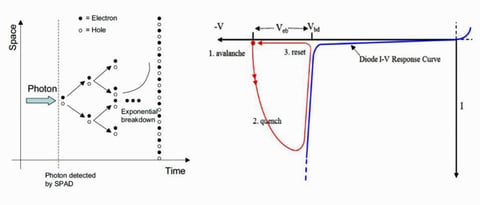
Figure 12 shows how the principle of distance measurement works using an SPAD cell sensor. The laser at X time emits a pulse which is reflected by the obstacle, and after Y time one (or more) photon reaches the sensor cell. The distance can be determined from the running time.
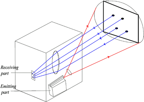
If one or several beams are radiated by rotating mirrors or micro-mechanical systems and there is a correspondingly large pad array of several cells, three-dimension objects can be detected. Figures 13 and 14 depict the two common LIDAR measurement procedures.
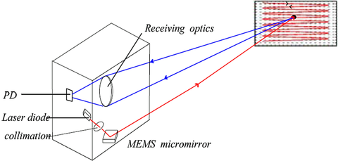
When using micro-mirror based on MEMS technology, the individual laser beam is radiated and reflected in a line shape. The reflected photons are evaluated by a corresponding optics sensor in the SPAD cell. Extreme demands are placed on the mirror system with regard to precision, service life, adjustability, and reliability. It is a system with movable components.
At the first glance, a system with no moving parts seems easier. In this system, several laser diodes (over 100) and an accordingly large receiver array are required. The laser diodes must be equipped with pulse widths in the nanosecond range and with currents of a few amperes, which poses a significant challenge to the semiconductor drivers.
Both systems are still works in progress. From the point of view of a semiconductor manufacturer the required semiconductors are technically feasible, whereas the area of the required SPAD array is not insignificant. New methods are needed for the activation and the control of the laser diode arrays if the target cost of around $100 is to be met. Corresponding MEMS are also in development.
Summary And outlook
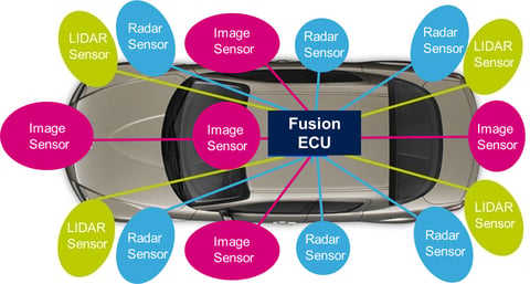
Driver assistance systems that enable autonomous driving from level 3 onwards will need at least three types of sensor systems: camera, radar, and LIDAR systems. As can be seen in Figure 1, several of each type of sensor operate at various locations on the vehicle. Although the necessary semiconductor technologies and development of the camera and radar sensors are already available today, the development of the LIDAR system poses the bigger and most dynamic challenge in technical and commercial terms.
Which of the systems we have discussed will prevail is difficult to predict. From a semiconductor perspective, the solid-state approach appears to be the most promising.
References
[1]https://crashstats.nhtsa.dot.gov/Api/Public/ViewPublication/812115
[2]http://www.monash.edu/__data/assets/pdf_file/0010/216946/muarc256.pdf
About the authors
Uwe Voelzke is the Technical Marketing Manager at STMicroelectronics in the Automotive and Discretes Group (ADAS). Uwe has a Master’s in Electrical Engineering from the Ruhr-University-Bochum (Germany) and has worked for STMicroelectronics since 1997. He has more than 20 years of experience in semiconductors with a focus on mixed-signal chip design and has held various marketing positions in charge of several Tier 1 and OEM automotive customers.
Gert Rudolph is the Technical Marketing Manager Automotive. STMicroelectronics. Gert has a degree in Communication Engineering from the University of Applied Sciences in Cologne and a Master’s in Electrical Engineering from the Ruhr-University-Bochum (Germany). He worked 10 years at ST as development engineer for integrated circuits mainly for automotive applications before he moved to Marketing. He held various Marketing positions at STMicroelectronics and is now responsible for strategic Marketing in the EMEA-Automotive and Discrete Group as Deputy Head of the Marketing & Application Department.
Evnoia Group is a corporate institution geared towards capacity building in the areas of good governance, sustainable development, leadership and economic development.
contact us
Prague, Czech Republic | +420 776 407 687
Baton Rouge, Louisiana, USA | +1 (315) 215-6251
gallery from past events


